
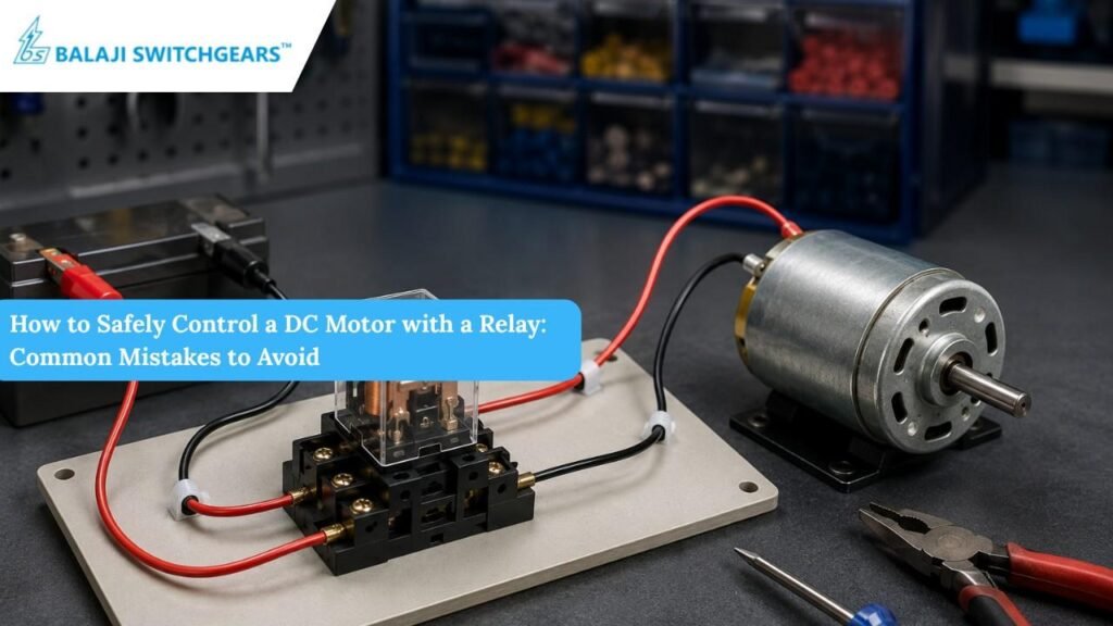
Power relays remain one of the simplest, most cost-effective ways to switch a DC motor – a pump, a fan, an actuator, a conveyor drive from a low-power control signal or low voltage relay trigger. Used within their rated limits, relays are a proven, reliable way to switch these loads. But a DC motor is an inductive, current-hungry load, and when relay contact rating, suppression, wiring, or switching duty aren’t matched to the application, the result is one of the most common causes of nuisance contact failures, welded contacts, and even fire risk on a panel.
This guide walks through what actually happens when a relay switches a DC motor, and the mistakes that most often turn a straightforward control circuit into a reliability headache.
Why DC Motors Are a Tough Load for a Relay
A relay’s datasheet rating is only a starting point. Datasheet ratings are defined under specific test conditions, and many headline current figures are resistive-load ratings rather than motor-load ratings. Before selecting a relay for a DC motor, check its DC switching capacity, inductive-load or motor-load rating (if published), derating curves, contact material, ambient temperature range, duty cycle, and expected electrical life. Two things make DC motors especially demanding on a relay’s contacts:
• Inrush current at start-up (closing stress). A stalled or just-starting DC motor can draw several times its running current closing a relay contact into that surge causes far more contact stress than the steady-state current shown on the motor’s nameplate.
• Inductive kickback at shut-off (opening stress). A motor winding stores energy in its magnetic field. When the relay opens the circuit, that stored magnetic energy forces current to keep flowing, and voltage rises until a new conduction path is created typically an arc across the opening contact gap. This arcing erodes contact material over time and, left unmanaged, can eventually weld the contacts shut. Locked-rotor and dynamic-braking conditions can create sustained transients that are even harder on the relay than a simple stop.
Because of this, the “current rating” printed on a relay is often a resistive-load number rather than a motor-load number. Motor loads need to be evaluated against the relay’s inductive or motor-load rating, which is typically a fraction of the resistive rating DC motor loads can require substantial derating, since DC arcs are harder to extinguish than AC arcs and motor inrush current can be several times the running current.
Mistake #1: Skipping Surge Suppression (Flyback Diode or Equivalent)
This is one of the most common and most damaging oversights in DC motor relay circuits. Without a controlled path for the inductive energy released when the motor coil’s field collapses a flyback diode across the motor terminals, a TVS diode, an RC snubber, a varistor, or contact-side suppression that voltage spike has to go somewhere, and it usually goes straight into the relay contacts as an arc, or into nearby semiconductors as a destructive transient. A diode across the motor is a common and effective choice for DC loads, but it slows current decay and can delay motor or relay release in applications where fast release matters; depending on response time, energy level, and contact-protection needs, a TVS diode, RC snubber, MOV/varistor, or contact-side suppression may be a better fit.
Fix: Provide a controlled path for the inductive energy, and select the suppression method based on supply voltage, motor current, switching frequency, release-time requirements, and the relay’s contact rating. A diode across the motor terminals, oriented to conduct only when the motor is switched off, lets the collapsing field current recirculate through the diode instead of arcing across the relay contacts, and remains a good default for many applications. For loads that switch faster or more frequently, or where fast release matters, an RC snubber, varistor, or TVS diode across the contacts may be a better fit.
Mistake #2: Confusing Continuous Current with Switching Current
It’s easy to size a relay against the motor’s steady running current and stop there. But several other numbers matter just as much: locked-rotor or start-up current, make current, break current, and, where applicable, dynamic-braking current. These don’t follow a single universal multiplication factor actual values depend on motor type, load inertia, supply voltage, and switching condition, so they need to be checked for the specific motor and application rather than assumed.
• Continuous load current what the relay carries once the motor is running, which determines thermal loading and heating of the relay’s contacts and terminals against its rated carry-current limit. This is necessary for sizing a relay, but it isn’t sufficient on its own.
• Switching current what the relay’s contacts actually have to make and break. This includes both make current (closing into a motor’s inrush) and break current (opening under load), and it determines contact erosion. For a motor load, it’s typically much higher than the running current, and the relay must be rated for the actual switching condition start-up, stopping, reversing, jogging, or dynamic braking if used.
A relay module chosen only against nameplate current may appear adequate on paper but can fail prematurely in service. Always check the manufacturer’s motor-load or inductive-load derating curve, not just the resistive-load figure, and size the relay against the switching current, not the running current.
Mistake #3: No Short-Circuit or Overcurrent Protection
A relay is a switching device, not a protection device. If a motor winding shorts or a wiring fault occurs downstream, an unprotected circuit lets fault current climb until something the relay, the wiring, or the motor is damaged. A correctly sized fuse, fuse module or circuit breaker upstream of the motor, matched to its current rating, is a basic safety requirement, not an optional extra.
Mistake #4: Underrated or Poorly Terminated Wiring
Every wiring terminal in the circuit is a potential source of resistance heating. Undersized conductors or loosely torqued terminals concentrate heat exactly where you don’t want it at a connection point next to plastic housings and insulation. Wires and terminal connectors must be sized to carry the motor’s actual switching current with margin, and if the Din Mount Relay is socket-mounted, the relay socket and its termination method need the same scrutiny as the relay itself. This is a frequent, and frequently underestimated, cause of field failures.
Fix: Size conductors to the motor’s actual (not nameplate-only) current draw, torque terminals correctly, and re-check connections after commissioning vibration or thermal cycling.
Mistake #5: Ignoring Ambient Temperature
Relay coil resistance, and therefore pick-up and drop-out relay coil voltage, shifts with ambient temperature. At the high end, coil insulation can degrade, and contact materials can be affected; at the low end, mechanical parts and lubricants can stiffen. It’s not enough to know the relay’s rated coil voltage you need to know the actual minimum and maximum ambient temperature the relay will see inside the enclosure, including heat contributed by neighbouring components, and confirm the relay is rated for that full range.
Mistake #6: Exceeding the Relay’s Rated Cycle Rate
Applications that switch a motor on and off rapidly jogging, dithering, or fast duty cycles add heating effects on top of normal load heating, and increase contact wear from more frequent arcing. A relay can become prematurely life-expired in an application that cycles faster than it was designed for, even if the current and voltage are both within spec. If your application needs frequent switching, check the relay’s rated mechanical and electrical life at your actual cycle rate, not just its continuous rating.
Mistake #7: Applying AC-Rated Habits to a DC Circuit
DC arcs behave differently from AC arcs – AC current crosses zero twice per cycle, which naturally helps extinguish an arc, while DC does not, so a DC arc can sustain itself and burn longer at the same voltage and current. As a rule of thumb, DC load voltages above roughly 24 V require deliberate arc-management measures (contact spacing, blowout magnets, or contact materials suited to DC switching) that a relay chosen purely for AC service may not have. Don’t assume a relay rated for a given AC voltage/current combination is safe to use at the same numbers on DC – check the relay’s specific DC rating.
Mistake #8: No Redundancy Where a Stuck Contact Is Dangerous
If a welded or stuck relay contact could put people or equipment at risk an actuator that can’t be commanded to stop, for example – single pole double throw relay should not be the only line of defence. Where failure consequences are serious, use double/redundant switching paths or a redundancy module and design the circuit so a single contact fault cannot leave the load permanently and unsafely energised. This is the same logic behind forcibly-guided (safety) relays, which are built specifically so contact welding can be detected by an external circuit rather than going unnoticed.
Mistake #9: Never Touching Live Terminals — and Assuming You Won’t Need To
It sounds obvious, but it’s worth stating plainly: never touch the terminal section of an interface relay or its relay socket while power is applied the risk of electric shock is real, and panel work under time pressure is exactly when this rule gets skipped. Always isolate and lock out power before wiring, testing continuity, or reseating a slim relay in its socket.
A Quick Pre-Commissioning Checklist
• Flyback diode, TVS diode, RC snubber, or varistor (surge suppression) fitted across the motor terminals or relay contacts
• Relay sized against inductive/motor-load switching current, not just running current
• Wiring and terminals sized and torqued for the real switching current
• Relay’s ambient temperature range confirmed against actual panel/enclosure conditions
• Cycle rate checked against the relay’s rated mechanical/electrical life
• DC-specific rating confirmed (not an AC rating applied to a DC circuit)
• Redundant switching in place if a stuck contact would be hazardous
• Lockout/isolation procedure in place before anyone touches live terminals
The Bottom Line
A relay-controlled DC motor circuit is only as safe as its weakest assumption. The datasheet gets you into the right ballpark, but the real risks arcing, thermal stress, undersized wiring, cycle fatigue shows up only when the relay meets your actual load, your actual enclosure temperature, and your actual duty cycle. Take the time to verify each of these against the real application before commissioning, and a basic relay-motor circuit will run reliably for years rather than becoming a recurring maintenance call.