
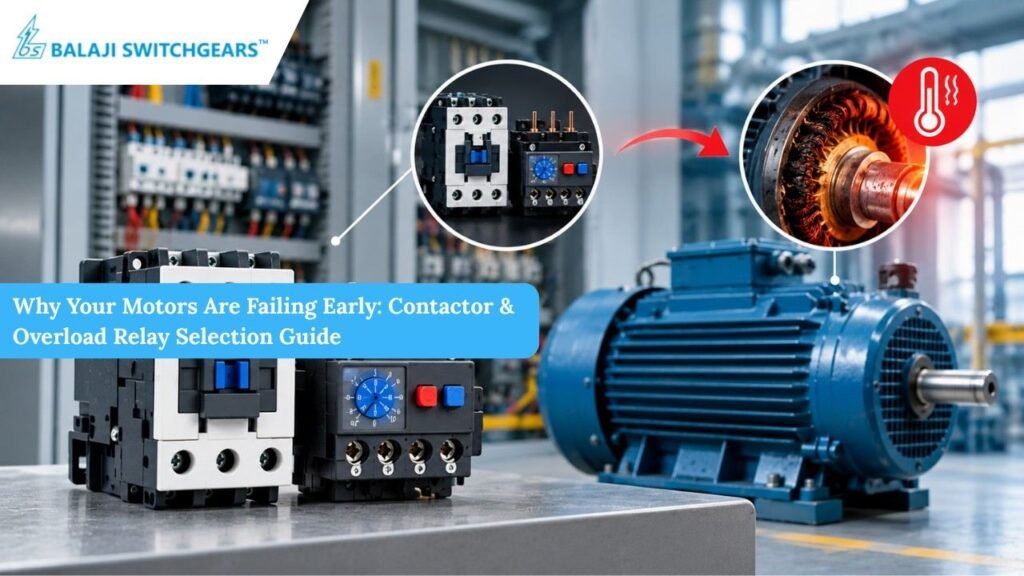
A motor rarely fails on its own. Walk through any plant that keeps rewinding the same machines and the real culprit is usually a few inches away inside the control panel: a contactor chosen for the wrong duty, or an overload relay set by guesswork. The motor takes the blame, gets rewound, and fails again within the year.
The good news is that most premature motor failures are preventable. They trace back to a handful of selection and setting mistakes repeated across factories, packaging lines and pump houses. This guide explains how contactor & overload relays protect a motor, where selection goes wrong, and how to get it right.
What the Contactor & Overload Relay Actually Do
These two devices are discussed together, but their jobs differ.
A contactor is the switch. It makes and breaks the power circuit to the motor thousands of times during its life, handling the heavy inrush current at start and the arc created at every opening.
An overload relay is the guardian. It watches the current drawn by the motor and trips the contactor when that current stays too high for too long. It does not stop short circuits; that is the job of a fuse or circuit breaker. Its purpose is to stop slow, silent damage that cooks insulation long before anything visibly breaks.
When either device is mismatched, protection fails quietly until the winding burns.
Mistake 1: Selecting the Contactor by Motor kW Alone
Many buyers pick a contactor by taking the motor rating and choosing the next size up. That feels safe, but it ignores the utilization category defined in IEC 60947-4-1.
AC-3 duty covers squirrel cage motors that are started and then run to a stop. Most fans and pumps fall here.
AC-4 duty covers jogging, plugging and inching, where the motor is repeatedly started and reversed. Here the contactor breaks currents several times higher than the rated running current.
A contactor rated for AC-3 at 22 kW may only be suitable for a much smaller motor under AC-4. Cranes, hoists and constantly cycling conveyors can destroy an undersized contactor in weeks. Pitted contacts raise resistance, create heat and cause voltage drop at the motor terminals.
Confirm the duty first, then match the rated operational current for that category, not the headline kW figure.
Mistake 2: Ignoring Starting Current and Frequency of Operation
A direct on line motor can draw six to eight times its full load current at the moment of starting. Heavy loads such as crushers and centrifuges hold that current longer because they accelerate slowly.
Two things matter: the make capacity, which must cope with inrush without welding contacts, and the number of operations per hour. A contactor performing 30 starts a day behaves very differently from one performing 30 starts an hour. Electrical life, which is quoted in millions of operations at AC-3, drops sharply as switching frequency and starting severity increase.
For high inertia loads or frequent cycling, size up deliberately and check the manufacturer’s electrical life curves.
Mistake 3: Choosing the Wrong Overload Trip Class
This is one of the most overlooked reasons motors burn early. Overload relays come in trip classes, such as Class 10A, 10, 20 and 30, which describe how long the relay tolerates a current of 7.2 times its setting before tripping.
Class 10 trips within 10 seconds and suits normal starting duty, such as light pumps and fans.
Class 20 allows up to 20 seconds and suits heavier loads with longer acceleration times.
Class 30 suits very high inertia applications.
Fit a Class 10 relay on a heavy load and it will be a nuisance trip during every start. Operators get frustrated, raise the setting or bypass the relay, and the motor is left unprotected. Fit a Class 30 relay on a small, light motor and the winding overheats before it reacts. Matching trip class to real starting time matters as much as the current setting.
Mistake 4: Setting the Relay Wrongly
The correct setting for an overload relay is based on the full load current printed on the motor nameplate, adjusted for the service factor and the supply conditions. It is not a number to raise until tripping stops.
A relay set too high gives a false sense of security. A motor running at 120 percent of its rated current may keep running for hours, while its insulation life shortens dramatically. A common maintenance rule says every ten degrees above rated winding temperature can roughly halve insulation life.
Set the dial at nameplate current, then verify with a clamp meter under load. If the motor keeps tripping, investigate the cause, which could be mechanical binding, bearing wear, a blocked fan or a low supply voltage, rather than raising the setting.
Mistake 5: Overlooking Single Phasing and Phase Imbalance
When one phase is lost, the remaining two phases carry far more current to deliver the same torque, and the motor overheats rapidly. A standard thermal relay may react too slowly in this situation, especially on a motor running below full load.
Choose overload relays with phase failure sensitivity, which reacts faster when currents become unbalanced. For critical motors, add a dedicated phase failure relay, or use an electronic overload relay offering imbalance and ground fault protection.
Mistake 6: Forgetting Ambient Temperature and Panel Heat
Panels in foundries, bakeries and hot outdoor installations can easily exceed 45 degrees Celsius inside the enclosure. Thermal overload relays are calibrated at a reference temperature, so in a hotter panel they may trip early, and in a very cold one, late.
Ambient compensated relays help, but panel design matters just as much. Allow spacing between devices, provide ventilation, and avoid mounting the relay directly above a heat source such as a drive or transformer.
Mistake 7: Coil Voltage, Control Circuit and Contact Maintenance
Even a perfectly chosen contactor fails if its control circuit is poor. Voltage dips on the coil supply cause chattering, so contacts open and close without proper pressure, creating arcing and welding. Dust, moisture and loose terminals add resistance and heat.
Check coil voltage under load, tighten terminals during scheduled shutdowns, and inspect contacts for pitting. Replace the contact kit before wear becomes a breakdown.
Coordination: The Part Everyone Forgets
A motor starter is a system: short circuit protective device, contactor and overload relay working together. IEC 60947-4-1 defines two types of coordination. Under Type 1, the starter may be damaged during a short circuit but must not endanger people. Under Type 2, the contactor and relay remain fit for use after a fault, with only light contact welding that is easily separated.
For continuous process industries, Type 2 reduces downtime and replacement costs. Use the manufacturer’s coordination tables when pairing a breaker or fuse with a contactor and relay, instead of selecting each device in isolation.
A Simple Selection Checklist
Before you finalize any motor starter, run through these points:
- Note the motor nameplate details: kW, full load current, voltage, service factor and efficiency.
- Identify the duty: AC-3 for normal running, AC-4 for jogging or reversing.
- Estimate the starting time and inertia of the load, then choose the overload trip class.
- Check operations per hour and the required electrical life of the contactor.
- Account for ambient temperature and enclosure ventilation.
- Confirm the coil voltage and control supply stability.
- Match the short circuit protective device to the contactor and relay using coordination charts.
- Set the overload relay to nameplate current, then verify with a meter under load.
Final Thoughts
A properly protected motor is one of the industry’s most reliable machines. Early failures usually mean the contactor and overload relay were selected for convenience instead of the actual application. Getting duty category, trip class, settings and coordination right costs very little compared with rewinding bills and production loss.
If you are unsure which combination suits your application, speak to a supplier who understands both the products and the plant floor. Balaji Switchgears, with more than three decades of experience in low voltage switchgear and industrial automation, supports OEMs, panel builders and end users with the right contactors, overload relays and complete starter solutions backed by PAN India service. To protect your motors, explore the range at Balaji Switchgears or contact the team for selection guidance. Choose Balaji Switchgears for dependable motor control that lasts.