
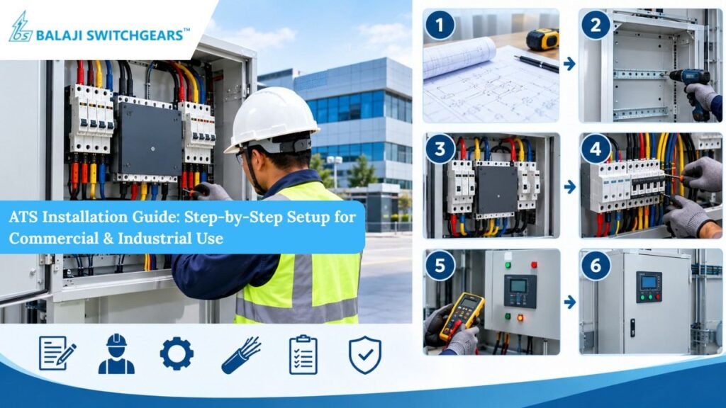
When the grid fails, every second counts. A hospital ward, a data room or a production line cannot wait for someone to flip switches by hand. An Automatic Transfer Switch, or ATS, does that job for you. It senses the loss of mains power, starts the standby source, and moves the load across without human involvement.
But an ATS is only as reliable as its installation. A loose lug, swapped neutral or badly set timer can turn a safety device into a failure point. This guide walks through ATS installation step by step for commercial and industrial sites, covering planning, wiring, settings and testing.
What an ATS Does and Why Installation Matters
An ATS connects a load to one of two power sources: the normal supply, usually the utility, and the standby supply, usually a diesel generator. It monitors the normal source continuously. When voltage or frequency drifts outside set limits, it signals the generator to start, waits for stable output, and transfers the load. When the mains returns and stays healthy, it retransfers and lets the generator cool down and stop.
The critical safety function is interlocking. The ATS must never connect both sources together, otherwise the generator can backfeed into the grid, endangering utility workers and equipment.
Know Your Switch Before You Begin
ATS units differ in design, so identify what you have.
Contactor-based units are compact and fast, suited to smaller loads.
Circuit breaker-based units use motorised breakers, offering protection plus transfer for higher ratings.
Dedicated changeover switches with motor operators handle heavy industrial currents.
Poles matter too. Three pole versions switch the phases only. Four pole versions also switch the neutral, which is generally required where the generator neutral is separately earthed, to avoid circulating currents and false earth fault trips. Check the product against IEC 60947-6-1, the standard for transfer switching equipment, including its stated class, such as PC or CB.
Step 1: Plan and Survey the Site
Good work starts before any tools come out.
Confirm the load. Identify the critical circuits that require backup power and calculate their total design load. Select an ATS with an appropriate rated current based on the calculated load, expected motor-starting currents, anticipated future loads and the manufacturer’s recommendations. Also verify that its short-circuit withstand rating is suitable for the available fault current at the installation point.
Check the sources. Record the voltage, frequency and phase sequence of both the utility supply and the generator. Verify that the phase sequence is compatible with the connected loads and the ATS manufacturer’s requirements.
Choose the transition type. Open transition, also known as break-before-make, briefly disconnects one source before connecting the other. Closed transition can minimise interruptions by briefly paralleling the sources, but requires suitable synchronisation and protective controls, along with utility approval where applicable.
Obtain approvals. Check applicable electrical codes, utility requirements and local regulations before connecting the standby generator to the installation.
Step 2: Select the Right Location
Place the ATS close to the main distribution board, in a clean, dry and ventilated room. Leave clear working space in front, normally around one metre, and keep the unit away from heat, vibration and flammable material. For dusty or damp areas, specify a higher IP rating enclosure. Mount it at a height where operators can read indicators and reach the manual override comfortably.
Step 3: Isolate and Make the Site Safe
Before touching any conductor, switch off and lock out both sources. Use a tested voltage detector on every incoming terminal to prove they are dead. Apply padlocks and warning tags, and keep the keys with the person responsible. Generators can start automatically, so set the controller to off and disconnect the start signal.
Step 4: Mount the Enclosure Securely
Fix the ATS to a flat, rigid surface using fasteners suited to its weight. Level the unit so mechanical interlocks move freely. Drill gland plates before fitting cables, and keep metal swarf away from live parts. Use temporary covers to protect the equipment from dust during the work.
Step 5: Connect the Power Cables
Most faults originate in the power connections.
Identify the terminals clearly. They are normally marked for Source 1 (normal), Source 2 (generator) and Load.
Size the cables for the full rated current, voltage drop and ambient temperature, and use the correct lugs for the conductor type.
Tighten every connection to the torque value in the manufacturer’s manual, using a calibrated torque wrench. Under-tightened lugs overheat, while over-tightened ones damage the terminal.
Maintain correct phase sequence on both sources, and keep L1, L2 and L3 consistent from input to output.
Support and clamp cables so that their weight does not stress the terminals.
Step 6: Handle the Neutral and Earthing Correctly
This is the most misunderstood part of the job. The neutral and earth arrangement depends on the system design.
If the generator neutral is bonded to earth at the generator, and the utility neutral is bonded at the service entrance, switching the neutral with a four pole ATS prevents parallel return paths. If the system has a single bonding point, a solid neutral through a three pole unit may be correct.
Whatever the scheme, connect the earth conductor firmly to the ATS earth terminal and bond the enclosure. Verify the arrangement with the system designer, since errors cause nuisance trips or leave hazardous voltage on metalwork.
Step 7: Wire the Control and Signal Circuits
Control wiring is lighter, but just as important.
Connect the generator start and stop signal, often a potential-free contact, to the generator controller’s remote start input.
Wire any auxiliary contacts for status indication, alarms or building management system feedback.
Use screened cable where noise is likely, and separate control wires from power cables.
Connect the emergency stop or inhibit input if the design needs it.
Label every wire at both ends to save time during fault finding.
Step 8: Set the Controller Parameters
Most modern ATS controllers allow adjustment of thresholds and time delays. Typical settings include:
Undervoltage and overvoltage limits, often around 80 and 110 percent of nominal.
Frequency limits around 90 to 110 percent.
Engine start delay of a few seconds, to ignore momentary dips.
Transfer delay, allowing the generator to stabilise before taking load.
Retransfer delay of several minutes, ensuring the mains is genuinely stable.
Generator cooldown time, usually a few minutes, to protect the engine.
Set these values per the generator manufacturer’s recommendations and record them in the commissioning report.
Step 9: Inspect Before Energising
Before applying power, check torque marks on all terminals and remove tools and debris. Run an insulation resistance test between phases and to earth, using a suitable megohmmeter and following manufacturer’s voltage limits. Check the mechanical interlock by operating the manual handle with the supply off.
Step 10: Test and Commission
Take a staged approach.
Energise the normal source and verify voltage, phase sequence and indicator status.
Run the generator separately, and confirm voltage, frequency and rotation.
Perform a manual transfer test, then an automatic one by simulating mains failure, for example by opening the upstream breaker.
Observe the sequence: generator start, delay, transfer, stable load, mains return, retransfer, cooldown.
Test under real load if possible, logging voltage and current.
Repeat the test several times, and confirm alarms and remote indications operate.
Give the client a signed test record, drawings and operating instructions.
Common Installation Mistakes to Avoid
Skipping torque checks on power terminals.
Swapping phase sequence between mains and generator.
Using a three pole unit when the neutral must be switched.
Setting the retransfer delay too short, causing repeated switching.
Leaving the ATS in manual mode after commissioning.
Neglecting proper labelling and drawings.
Maintenance Tips for Long-Term Reliability
An ATS sits idle for months, then must work in seconds. Schedule a monthly test transfer, and carry out an annual inspection that includes thermography, terminal retightening, cleaning, and checking of contacts and interlocks. Keep spare coils and fuses in stock.
Final Thoughts
A well-installed ATS gives a business quiet confidence that power problems will not turn into production loss. Careful planning, correct neutral treatment, disciplined wiring and thorough testing are what make that confidence justified.
If you need help choosing or commissioning an ATS for your plant, rely on a supplier with practical experience. Balaji Switchgears has served OEMs, panel builders, contractors and end users across India for over 36 years, supplying low voltage switchgear and automation products, along with panel commissioning support and PAN India service. Talk to Balaji Switchgears for guidance on the right ATS and its setup. For dependable standby power, choose Balaji Switchgears.